Saturday, May 30, 2020

Baseboard Construction

Foamcore board has its advantages, but it can easily warp if proper bracing is not used.  The baseboard is NOT constructed on top of a single sheet of foamcore, but built as a box.  The layout thickness is 1 1/2 inches.

I use 2 sheets of foamcore from Elmer's.  I prefer the black paper over the white.  The black paper seems to be more durable than the white.  Well, at least for me it does.  Using black can be difficult when using pencil marks.  I have no problem seeing these marks, but if you use black foamcore, you may want to use a white colored pencil.


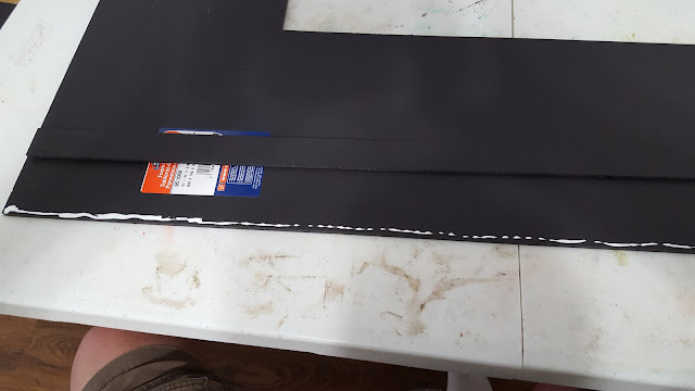
I measure out the baseboard sides and braces using the dimensions on the Sketch Up diagrams in my previous post.  I will be using a cutter called the "Master Airscrew Balsa Stripper" by Windsor Propeller Company.  I purchased mine from a local hobby store, but Micro Mark has them as well.  I use a standard #11 blade.  I have tried bigger blades, but the #11 works the best. I used a smaller cutting board due to my large board being in storage.  A larger board works better.  I use Formula 560 Canopy Glue for layout assembly.  Any waterproof PVA will work.  I am not a fan of using hot glue for foamcore baseboard construction.  I have had glue joint failures in the past with hot glue.


I tack the track in place on the baseboard with push pins, and trace around the track (not pictured).

Next, I remove the track and push pins, then I use T-pins to assemble the baseboard edges.  I use them liberally throughout the assembly process to make sure I have good contact with the glued surfaces.


I continue this process for the end braces and the inner support braces following my measurements from the Sketch Up diagrams (end brace assembly not pictured).


I also constructed the clips that will connect the tail track to the main baseboard from foamcore. 


The completed baseboard box with foamcore clips attached.


The tail track boxes are constructed the same way as the main baseboard.  The following photos show the underside of the baseboard and the placement of the clips and the tail track sections.


additional support bracing will be added before wiring


The completed baseboard with tail tracks connected. 


Up Next: Track Installation


Tom

Saturday, May 23, 2020

Baseboard Design

I have been working with Sketch Up to create the design of the Herrin Micro foam core baseboard along with the foam core clips that connect the sections together.  Please keep in mind that I am a novice at using design cad and I am sure there are a few errors in my work.  I would have used my hand-drawn sketches, but they are not "sharing worthy," aka not legible to anyone but myself!

Feel free to modify the measurements to suit your micro layout needs.  I would suggest keeping end sections of the baseboard no wider than 24 inches.  Multiple connecting clips may be needed for widths wider than this.

The Baseboard:

baseboard top


The Underside of the Baseboard:

underside of baseboard


Placement of Clipboard and Support Braces:

be sure to keep the 3/4 inch end braces accurately spaced to 1 1/2 inches


Tail Track Baseboard Sections:

tail track tops

clip connection brace locations


angle view (3/4" end braces are 1 1/2" in from edge) 


Right-side Clips (x2)  [1.5 x 8 inches]

Top view of right clip (x2) 


Left-side Clip (3.5 x 8 inches)

left-side clip


left-side clip


Please leave a comment if you have any questions about these designs.

Thanks!
Tom

Friday, May 22, 2020

The Track Plan

I like to use SCARM for track planning.  This is a freeware track planning program that is fairly easy to learn. I'll post a link to their site at the bottom of this post.
The layout size including tail tracks is 523 inches. 

The Herrin Micro Track Plan:


Work on the baseboard is already completed.  I'll be posting photos of that next.

SCARM Track Planning Web Site
 https://www.scarm.info/index.php

Tom

History Highlights of the Prototype

Photo by Terry Redeker (used with permission) 


The Herrin branch line was constructed in 1895 by the Chicago & Texas connecting Carbondale, Illinois with Herrin.  Eventually the line was taken over by the Illinois Central (IC).  Many years later, the connection to Carbondale was cut and the city of Herrin purchased the tracks that run through the town in 1987.  A connection with the Burlington Northern was built to the east of town.  The Crab Orchard & Egyptian (C.O.& E.) would run the line until 2019 when the Herrin Railroad LLC was created to operate the line.

You can find out more interesting information about the railroads in the Carbondale area at the following web site...


The Herrin Micro will feature the Maytag Plant as the main subject of the layout. Unfortunately, the Maytag plant closed in 2006.  Stone Container, another manufacturer on the line, closed as well.  The C.O.& E. served a few other industries on the line until they eventually closed too.  The line was used to store rolling stock, but that is no longer the case.  The tracks have sat idle since 2011, but that is supposed to change in the near future with the formation of the Herrin Railroad LLC.  

Photos of mine from Herrin in 2015:


Tom

Welcome to the Herrin Micro

This blog will follow my progress of building a micro layout of a scene located in Herrin, Illinois. This micro layout fits in a space of 493 square inches, and will be in HO scale. The layout baseboard will be made from foamcore using a clipboard method originally developed by Chris Ellis.

A special "thank you" to Terry Redeker for the use of the photo. This photo shows the Crab Orchard and Egyptian (COER) 1136 switching cars at the Maytag plant. The very scene I wish to model!


Please be sure to visit Terry's wonderful rail video and photography page on Facebook at...

https://www.facebook.com/Redeker-Rail-Video-Photography-133532949995359/

Thanks again, Terry!

Tom Conboy